The practical answer.
Verify the battery temperature path from the sensing element to the equipment's charging decision. Request the sensor resistance curve and its tolerance, confirm the sensor's physical location and determine which circuit sets the thresholds. On a controlled bench, record actual charging behavior with nominal, boundary and simulated sensor-fault inputs. Have the device manufacturer approve the acceptance criteria and the response for the complete equipment.
- A sensor specification needs the resistance curve and its tolerances across the reviewed range.
- Validate charge response and operator indication independently.
- Tie every result to the pack, charger and software revisions used for the test.
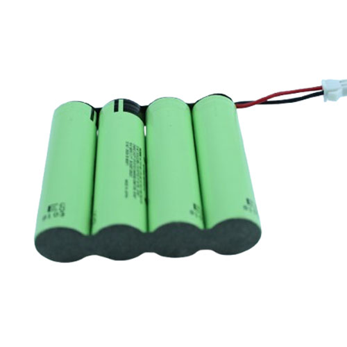
Follow the temperature signal to the charging decision
A temperature reading can reach the charger through a pack thermistor, through an embedded battery-management controller, or through the equipment's own electronics. Draw the actual signal path and write down which element decides whether current may flow. A temperature shown on a screen may come from a different location than the value controlling charge. Where the system has multiple sensors, name each signal and define its purpose in the review record.
For a negative temperature coefficient thermistor, abbreviated NTC, request the resistance-temperature table and tolerance over the temperatures relevant to charging. Ask where the sensor sits in the pack and how its location and attachment are controlled in production. The temperature of a cell, the pack surface and air in the equipment compartment can differ during heat-up or cool-down. Validate which location the equipment's decision is intended to represent.
Why a room-temperature resistance check can miss a mismatch
Two components can both measure 10 kΩ at one reference temperature while having different resistance values near the warm and cold thresholds. Texas Instruments' BQ25302 data sheet illustrates how resistance values at the intended boundaries inform the surrounding resistor network. Its BQ25120A data sheet describes a different charger arrangement with configurable host behavior and a voltage-based thermistor input. These examples show why the component curve and the full sensing circuit belong in the same review.
For a simplified check, imagine a 3.3 V supply, a 10 kΩ pull-up and a thermistor from the sense node to ground. The ideal sense voltage is 1.65 V at 10 kΩ. If the thermistor reads 4.9 kΩ at a selected warm test point, the same circuit gives approximately 1.09 V. A hypothetical replacement that reads 6.0 kΩ at that point gives approximately 1.24 V. The 0.15 V difference is large enough to compare against the actual threshold margin. This example ignores tolerances and is not a charger configuration recipe.
Capture evidence from sensor emulation and complete equipment
A qualified engineering team can use an approved bench fixture or simulator to emulate the sensor's electrical values without overheating a production pack. Record the fixture accuracy and the circuit boundary. Confirm the intended operation on the assembled equipment using the manufacturer's authorized verification plan. Electrical emulation alone does not verify the physical sensing location or thermal response time.
Measure charge current at the defined point as well as the charger status, equipment event log and operator-visible indication. A stopped current may reflect a full battery, a missing supply or a sensor decision. Record the starting state and the condition you changed so the result identifies the cause.
If the device accepts an external power source while operating, use the operating modes from the approved test plan. A pack can be inhibited from charging while other equipment circuits remain powered. Give the test record separate fields for battery current, device operating state and the displayed indication. For an intermittent input, record whether the observation occurred before or after any intentional filtering delay. This helps the design team explain a difference between a transient reading and a latched fault.
| Bench state | What to observe | Evidence to retain |
|---|---|---|
| Normal sensor values | Charging behavior with the approved pack and supply | Measured sensor value, current, charger state and software revision |
| Values near both boundary regions | Transition, tolerance margin and any specified hysteresis | Applied value, measured transition and conditions |
| Simulated open or short | Equipment-defined fault handling and indications | Separate record for each fault, timing and event message |
| Restored valid reading | Whether charging resumes and what the device requires first | Recovery sequence and measured current |
| Physical sensing review | Sensor placement and temperature tracking in the installed assembly | Placement drawing, test method and correlated readings |
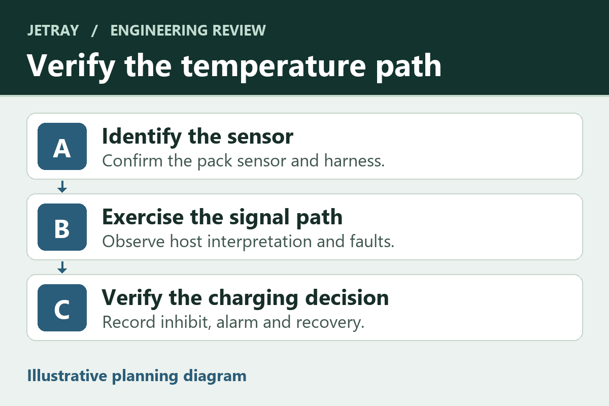
Keep supplier evidence and device acceptance in the same change record
Put the pack revision, thermistor part or curve reference, charger hardware and firmware version on one page. Add the sensor circuit, threshold specification, approved test method and observed response. If the supplier changes the sensing element, mounting position or battery-management firmware, the equipment team should be able to identify which evidence is still applicable.
Jetray lists medical equipment as an application direction and publishes pack formats that can begin an engineering discussion. When comparing compact and multicell evaluation references, request the sensor implementation for the proposed configuration and share the equipment charging architecture. Keep pack catalogue information separate from the device manufacturer's design and regulatory decisions. For an applicable U.S. 510(k) device, the cited FDA guidance addresses the assessment of changes to an existing device.
Temperature verification questions for the design review
Which part owns the decision to suspend charge?
Trace the actual implementation. It may include a charger input, host logic and independent battery protection. Verify each required layer under its own documented conditions and record the result at the equipment boundary.
Can a successful bench fault test establish thermal performance?
Use simulated inputs to verify logic and instrument response. A separate assembled-device test is needed where the project requires evidence of sensor placement, coupling or temperature lag.
Sources & further reading
- Texas Instruments BQ25302 data sheet, thermistor temperature monitoring ↗
- Texas Instruments BQ25120A data sheet, external NTC monitoring and threshold behavior ↗
- FDA guidance on deciding when to submit a 510(k) for a change to an existing device ↗
- Jetray single-cell battery pack catalogue reference ↗
The circuit values and bench scenarios are illustrative. A device design team should approve equipment-specific thresholds, fault responses and verification. U.S. FDA guidance is included for device change assessment and is specific to its stated scope.
Prepared for the medical equipment battery projects collection. General engineering guidance does not replace a model-specific datasheet or application validation. Source review: 5 November 2026.