The practical answer.
Review the battery, charger and system rails as one state-based power path. Adapter presence does not prove that the battery is charging, and a charging symbol does not establish readiness after mains loss. Define the permitted states, measure current at the correct nodes, and validate transitions in the complete equipment. The equipment manufacturer must determine the required continuity and fault response; this guide does not prescribe clinical behavior or establish medical-device approval.
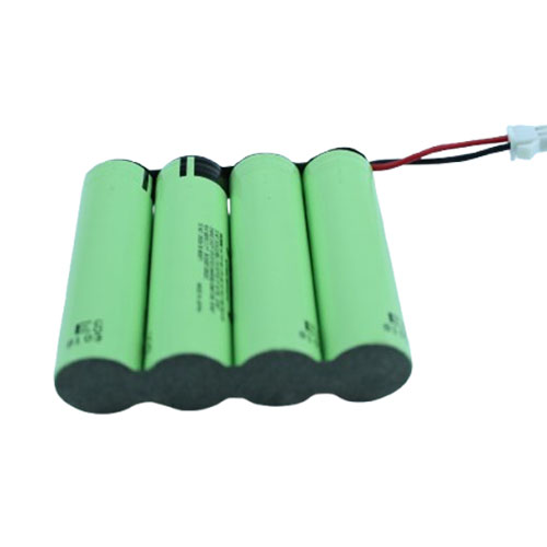
Map the rails before interpreting a charging icon
Begin with a drawing that distinguishes the external adapter, its input connector, the charger input, the system supply and the battery terminals. Label where current is measured and which rail powers the application processor, display and other subsystems. Without this drawing, a positive charger-input current can easily be mistaken for current entering the battery. Treat direction conventions as part of the drawing, so firmware, test equipment and supplier reports use the same sign for charging and discharging.
Next, write the operating states separately: adapter-only operation where supported, battery-only operation, simultaneous operation and charging, battery supplement operation, suspended charging, and a powered-down service state. Some architectures do not support every state. An absent or unsuitable state is an integration question, not a reason to assume a catalogue pack must provide it. TI's BQ25672 illustrates a charger architecture with a power path and battery supplement operation; that example does not identify the circuit fitted inside any Jetray reference.
Budget available input power and the active equipment load
Use a power budget at defined measurement boundaries. A hypothetical design receives 30W at its regulated system input while its active electronics use 22W. Before additional charging-path losses or limits, only 8W remains for the battery. If the electronics briefly demand 34W, the same input cannot simultaneously supply that demand and a positive charging allowance. Depending on the approved architecture, the battery may supplement the system, a load may be limited, or the rail may fall. No particular response is assumed here.
These numbers are arithmetic examples, not adapter recommendations, medical-equipment requirements or Jetray test results. Repeat the budget using measured operating states rather than an attractive average. Display brightness, radios, motors and accessory startup can change the balance. Ask the charger designer which constraints dominate when input current, input voltage, battery temperature and internal thermal regulation compete. The useful output is a bounded charging capability under each equipment mode, not a single maximum charger-current number copied into a specification.
| Observed state | Evidence to collect | Decision owner |
|---|---|---|
| Adapter present; no positive battery current | System load, charger state and current direction at battery terminals | Equipment and charger teams |
| Adapter removed under active load | Synchronized rail, current and status trace | Equipment validation team |
| Charging temporarily inhibited | Reason code, validity and approved recovery behavior | Battery/charger interface owners |
| Replacement battery connected | Identity, revision and initialization record | Equipment service and engineering teams |
Evaluate source loss as a transition rather than a static voltage check
A system can operate acceptably from either source in isolation yet behave differently during transfer. Define the beginning and end of the transition, identify the equipment rails that matter, and agree which signal indicates an approaching power problem. Analog Devices' LTC2952 is an example of hardware combining source selection with supervision and a shutdown interface. Its existence illustrates the distinction between selecting a power source and coordinating the equipment response; it does not imply that this component is required or used in the proposed pack.
A responsible engineering team should examine the transition at more than one battery condition and system load. A fresh, warm sample at a light load does not represent every intended state. Capture rail voltage, pack current and relevant status signals against one timebase. Confirm whether a communication event is reported before or after a rail disturbance. A polling log with widely spaced samples may miss the event that resets a processor, so the measurement bandwidth must be chosen for the question rather than for convenient spreadsheet size.
Separate charging status, energy state and permission to operate
Create a signal dictionary before choosing dashboard wording. External power available, charging enabled, positive battery current, charge complete and battery ready are different statements. The responsible device team must decide how its user interface represents them. A battery can be connected to an adapter while charging is inhibited, while a system load consumes the available input, or while battery charge is already complete. None of those conditions should automatically be translated into the same message without a defined meaning.
The dictionary should specify source, units, update interval, validity and behavior when the source disappears. Consider whether a last-known reading is visibly stale or silently retained. For example, losing a temperature message must not accidentally make an old charging-permitted flag look current. This is an interface review principle, not a universal alarm prescription. Do not describe a catalogue battery, a generic communication bus, or an indicator LED as providing a finished medical device's validated readiness decision.
Include insertion, storage and service states in the same review
An engineering evaluation should distinguish a low-energy battery from an electrically disconnected one. Request the approved wake-up, connection and service procedures rather than improvising a recovery method. The equipment may encounter a replacement battery after storage, a pack with a different learned state, or a device configuration that was powered from an adapter during service. Those are useful scenarios for an interface specification, but the exact handling sequence and any restrictions must come from the released device and battery documentation.
Pay attention to which subsystem retains identity and configuration after removal. A host that recognizes a connector but never checks the approved battery identity can display familiar values for an unintended component. Conversely, a legitimate replacement may require a documented initialization process. Record these decisions without assuming that every pack contains a fuel gauge, authentication device or communication processor. The three medical catalogue entries on this site are application-evaluation references; their labels do not establish those capabilities or a release for a particular device.
Build a controlled transition evidence set
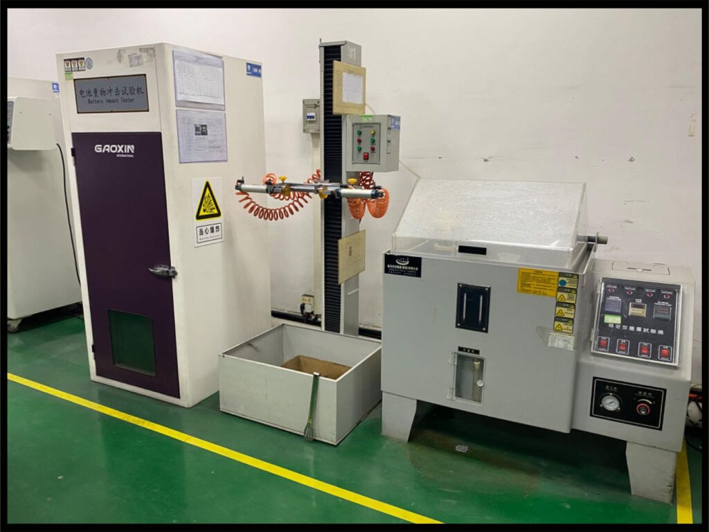
Start the test plan with a question and a pass criterion written by the equipment team. One example is whether a specified system rail remains within its approved window through an adapter-removal event. Another is whether a stale battery message becomes identifiable to the host within the approved time. Choose sample identity, state preparation, loads, environmental conditions and measuring instruments that can actually answer the question. A screenshot showing a green charging icon cannot substitute for the missing electrical and software evidence.
Preserve unsuccessful traces as well as successful ones. Include the adapter version, cable assembly, charger configuration, pack revision and device firmware in the report. If a test depends on a service mode, state that clearly so it is not confused with normal operation. Begin with a controlled engineering setup and an agreed risk assessment; this article is not an instruction to interrupt power on equipment in service. Qualified personnel should execute the device manufacturer's approved validation procedures and decide whether further review is necessary.
Turn observations into specific procurement decisions
A useful supplier question is narrower than asking whether the battery works while charging. Ask which terminals may deliver energy in each state, what enables or blocks each current direction, what host information is available, and what evidence can be supplied for the proposed assembly. Link the answers to the exact pack drawing and interface revision. If an answer depends on equipment-side hardware, identify that dependency instead of assigning the whole result to the battery supplier.
For a Jetray discussion, the compact 3.6V evaluation and the 14.8V evaluation provide different starting architectures, not interchangeable candidates. The 11.1V evaluation adds another configuration requiring its own review. Request the current approved specification for the actual proposal rather than treating these catalogue labels as a common charging interface. Send the state drawing, measured load traces and unresolved interface questions to [email protected]. Keep component selection, device validation and any regulatory assessment as separate recorded decisions.
Frequently asked questions
Can the equipment run while the battery charges?
That depends on the complete power-path implementation, input budget and approved operating conditions. A charger that supports a system rail can still reduce charging current when equipment demand rises. Establish whether the battery is charging, supplementing or neither by using measurements at the defined battery boundary. Permission to operate the finished equipment in a particular state must come from its manufacturer, not from this general discussion.
Does automatic source switchover guarantee uninterrupted device operation?
No. A source-selection function is only one element. Rail tolerance, downstream conversion, current demand, control timing and software behavior all affect the result. The equipment team must define what continuity means for its product and obtain evidence for the evaluated configuration. This guide neither sets an acceptable interruption interval nor establishes clinical suitability.
Does a charger datasheet certify the medical battery?
No. Semiconductor documentation explains the behavior of that component under stated conditions. It does not establish which circuit a supplier used, whether the assembled battery matches the example, or whether the finished device is approved. The linked Jetray entries remain application-evaluation references, and the device manufacturer retains responsibility for the complete product assessment.
Sources & further reading
- Texas Instruments BQ25672: NVDC power-path and battery supplement operation ↗
- Analog Devices LTC2952: source switchover and supervised shutdown ↗
- Jetray original product and application navigation ↗
Prepared from primary technical sources and original engineering analysis. All numerical scenarios are hypothetical planning examples, not Jetray measurements, customer cases or verified product ratings. Catalogue links are evaluation references; exact application suitability and approval require documented project validation.
Prepared for the medical equipment battery projects collection. General engineering guidance does not replace a model-specific datasheet or application validation. Source review: 5 November 2026.